Stress Corrosion is type of corrosion which occurs due to the combined action of Tensile Stress and corrosive environment. Stresses may be Residual or Applied.
Corrosive environment act at existing crack crevices. Tensile stresses pull the metal apart at the crevices & exposes new metal to corrosive environment…….. This way attacked crack surfaces will propagate & will result in brittle failure of the metal.
Residual Stresses ------------> Due to cold working of Metal
Applied stresses -------------> Applied Internal Pressure
Corrosive Environment -----> Chloride, H2S in water
Sunday, November 30, 2008
Thursday, November 27, 2008
The Allowable Stresses Limits as per ASME VIII Div.2
The Allowable Stresses Limits should be determined and will be compared with actual stress occured on structure. This value is taken from ASME BPV Sect II part D.
And the limits can be taken from ASME VIII div 2 as follow:
Primary Membrane and Bending (combined) Stress Intensity = 1.5 fallow
Local Membrane and Bending (combined) Stress Intensity = 3 fallow
Stress intensity is defined as twice the maximum shear stress (which is equivalent to the difference between the largest principal stress and the smallest principal stress as a given point).
Primary membrane stress refers to a membrane stress occurring across thickness of any section or is average stress across full width.
Primary Membrane and Bending (combined) Stress Intensity refers to primary membrane stress plus bending stress excluding secondary and peak stresses.
Local Membrane and Bending (combined) Stress Intensity refers to primary membrane stress plus bending stress including secondary stress but not peak stresses.
Secondary Stress refers to normal stress or shear stress developed by the constraint adjacent parts or by self-constraint of a structure.
Peak Stress refers to stress which does not cause any noticeable distortion and is objectionable only as a possible source of fatigue crack or brittle fracture.
Tuesday, November 25, 2008
The Resonance
In physics, resonance is the tendency of a system to oscillate at maximum amplitude at certain frequencies, known as the system's resonance frequencies (or resonant frequencies). At these frequencies, even small periodic driving forces can produce large amplitude vibrations, because the system stores vibrational energy. When damping is small, the resonance frequency is approximately equal to the natural frequency of the system, which is the frequency of free vibrations.
Resonant phenomena occur with all types of vibrations or waves: there is mechanical resonance, acoustic resonance, electromagnetic resonance, and resonance of quantum wave functions. Resonant systems can be used to generate vibrations of a specific frequency, or pick out specific frequencies from a complex vibration containing many frequencies.
In this chapter will be shown the resonance of the motor mount structure. The motor type is VSD motor, and will be operated at 60%,70%,80%,90%and 100% maximum at 345rpm.
The result shown that the resonance occur at 50% and 90% of the motor operation. This resonance is occur between motor and structure it self. So the final conclusion is operatio on those phase (50% and %90) is not recomended to avoid resonance between motor and structure.

Thursday, November 20, 2008
Flow Around A Baseball USING FLOTRAN
Introduction: In this example you will model air flow over a baseball.
Physical Problem: Compute and plot the velocity distribution over the baseball shown below.
Problem Descriptio n:
n:
· A Baseball is 7.48 cm in diameter. (radius of 3.74cm)
· The flow velocity (of air) over the baseball is approximately 40 m/s.
· Objective:
To plot the velocity profile around the ball.
To graph the velocity distribution above and below the ball.
· You are required to hand in print outs for the above.
· Figure:

IMPORTANT: Convert all dimensions and forces into SI units.
· Create the larger area, then the area defining the baseball.
· Subtract the baseball area from the larger area.
· Define the Element Properties as a 2D Air Element
· Define the Material Properties of the Air Element (Density and Viscosity are the important qualities)
| Mesh the plate with a mesh size of 0.005 on the edges of the baseball, and 0.2 on the edges of the outer area. | |
| Apply Boundary Conditions (No Slip along the edges of the baseball, velocity along the left line of the large area, and Atmospheric Pressure (P=0 in ANSYS) along the top, right and bottom lines of the large area. | |
| Iterate 20 times and solve. (Ideally the iteration count would be at least several thousand times to make sure that the solution converges… but computational time dictates that in order to be able to solve the problem in a reasonable amount of time, the iteration number should be trimmed down to 20) | |
| Plot the Velocity distribution in the X and Y directions, this is the answer you should obtain with 20 iterations:
|
(Contour Plot)

(Vector Plot)

Monday, November 17, 2008
How to provide vibratiob calculation on FEA
You use modal analysis to determine the natural frequencies and mode shapes of a structure. The natural frequencies and mode shapes are important parameters in the design of a structure for dynamic loading conditions. They are also required if you want to do a spectrum analysis or a mode superposition harmonic or transient analysis.
You can do modal analysis on a prestressed structure, such as a spinning turbine blade. Another useful feature is modal cyclic symmetry, which allows you to review the mode shapes of a cyclically symmetric structure by modeling just a sector of it.
Modal analysis in the ANSYS family of products is a linear analysis. Any nonlinearities, such as plasticity and contact (gap) elements, are ignored even if they are defined. You can choose from several mode-extraction methods: Block Lanczos (default), subspace, PowerDynamics, reduced, unsymmetric, damped, and QR damped. The damped and QR damped methods allow you to include damping in the structure. The QR Damped method also allows for unsymmetrical damping and stiffness matrices. Details about mode-extraction methods are covered later in this section
Monday, November 10, 2008
Shell 63
SHELL63 has both bending and membrane capabilities. Both in-plane and normal loads are permitted. The element has six degrees of freedom at each node: translations in the nodal x, y, and z directions and rotations about the nodal x, y, and z-axes. Stress stiffening and large deflection capabilities are included. A consistent tangent stiffness matrix option is available for use in large deflection (finite rotation) analyses.
Tuesday, July 8, 2008
Meshing Density Effect in FEA
Mesh density is extremely important. If your mesh is too coarse, your results can contain serious errors. If your mesh is too fine, you will waste computer resources, experience excessively long run times, and your model may be too large to run on your computer system. To avoid such problems, always address the issue of mesh density before you begin your model generation.
Perform an initial analysis using what seems to you to be a "reasonable" mesh. Reanalyze the problem using twice as many elements in critical regions, and compare the two solutions. If the two meshes give nearly the same results, then the mesh is probably adequate. If the two meshes yield substantially different results, then further mesh refinement might be required. You should keep refining your mesh until you obtain nearly identical results for succeeding meshes.
In this case, increased mesh density will be provided at junction between nozzle and header box of Air Cooler Heat Exchanger.
 First, normal mesh density with 30mm length was given at the whole model. The stress intensity was given at 237.157MPa
 And for second analysis, mesh density increased by 2 times, and the result increased at 323.598MPa.
 And after re-run the anysis with increasing the density, we obtain:
Sunday, July 6, 2008
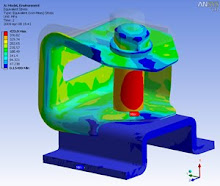
Bulkhead Stress Intensity

The analyzed Filter element bulkhead was designed to withstand pressure load of 125 psig (0.861875 MPa) as structural component as specified on Pressure vessel datasheet for Acid Gas Removal System.
A FEA model and Stress analysis of Filter element bulkhead was built and run using the ANSYS 9.0 finite element software.
Pressure load = 0.861875 M.Pa (125 psig) apllied on 76 mm thickness of Bulkhead.
The Max. Local Primary Membrane Stress is 32.8 MPa (4757.25 psig) is created on filter element Bulkhead due to pressure load, this is acceptable as allowable stress = 1.5*137.9 MPa = 206.85 (30000 psi
Friday, July 4, 2008
Pressure Vessel under cyclic loading
 The analysed Molecular Dehydration vessel (SK-30-V-01 A/B) was designed to withstand a thermal cyclic operation
Internal Pressure 6.89 MPa as operating pressure applied to internall surfaces. And thermal Cylclic applied at surfaces of inlet and outlet nozzle as per data shown:
The fatigue analysis was carried-out in accordance with ASME B&PV Code, Section VIII Division 2 Appendix 5 (2004 ed). As cycling loading is due to the thermal and pressure, the result shown in the table above were used for the fatigue life assessment.
 The output quantity is the stress intensity (SINT-MPa). This is calculated by the program as the largest of the absolute values of differences between principal atreses S1,S2 & S3 (where: S1>S2>S3):
SINT = max {│S1-S2│,│S2-S3││S3-S1│}.
Thus, this is equivalent to Tresca stresses: S = S1-S3
 The alternating stress intensity was calculated based on the maximum difference between conditions operating and stan-by operation:
Srij = 375.063 – 256.89 = 172.057 MPa
Correction Factor for increased temperature = Eo/Et
Eo = 207 GPa ( as used for S-N curve in the code )
Et = 189 GPa ( at temperature of 315 oC )
Thus, Eo/Et = 1.09
Srijcorr = 1.09 x 172.057 = 187.542 MPa
So, Sa = 0.5 x 128.809 = 93.3771 MPa
From S-N curve in the Code, number of cycles is 505 cycles (13670 years).
Failure Analysis in Air Cooler Structure
 This report perform deflection, stresses and slenderness ratio analysis acting to whole air cooler structure due to various loading (dead load, live load, combination load etc). The stresses resulted from the combined load, in turn, were compared with the allowable stress.


Plate stress both primary and local stress due to combined bending and membrane stress still covered by allowable design stress specified by ASME VIII Division 2-2004 + 2005 Edition Pressure Vessel code and ACHE specification
Subscribe to:
Posts (Atom)