Tuesday, July 8, 2008
Meshing Density Effect in FEA
Perform an initial analysis using what seems to you to be a "reasonable" mesh. Reanalyze the problem using twice as many elements in critical regions, and compare the two solutions. If the two meshes give nearly the same results, then the mesh is probably adequate. If the two meshes yield substantially different results, then further mesh refinement might be required. You should keep refining your mesh until you obtain nearly identical results for succeeding meshes.
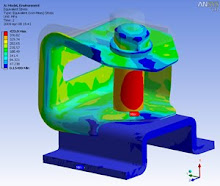
In this case, increased mesh density will be provided at junction between nozzle and header box of Air Cooler Heat Exchanger.
First, normal mesh density with 30mm length was given at the whole model. The stress intensity was given at 237.157MPa
And for second analysis, mesh density increased by 2 times, and the result increased at 323.598MPa.
And after re-run the anysis with increasing the density, we obtain:
Sunday, July 6, 2008
Bulkhead Stress Intensity
The analyzed Filter element bulkhead was designed to withstand pressure load of 125 psig (0.861875 MPa) as structural component as specified on Pressure vessel datasheet for Acid Gas Removal System.
A FEA model and Stress analysis of Filter element bulkhead was built and run using the ANSYS 9.0 finite element software.
Pressure load = 0.861875 M.Pa (125 psig) apllied on 76 mm thickness of Bulkhead.
The Max. Local Primary Membrane Stress is 32.8 MPa (4757.25 psig) is created on filter element Bulkhead due to pressure load, this is acceptable as allowable stress = 1.5*137.9 MPa = 206.85 (30000 psi
Friday, July 4, 2008
Pressure Vessel under cyclic loading
Internal Pressure 6.89 MPa as operating pressure applied to internall surfaces. And thermal Cylclic applied at surfaces of inlet and outlet nozzle as per data shown:
The fatigue analysis was carried-out in accordance with ASME B&PV Code, Section VIII Division 2 Appendix 5 (2004 ed). As cycling loading is due to the thermal and pressure, the result shown in the table above were used for the fatigue life assessment.
The output quantity is the stress intensity (SINT-MPa). This is calculated by the program as the largest of the absolute values of differences between principal atreses S1,S2 & S3 (where: S1>S2>S3):
SINT = max {│S1-S2│,│S2-S3││S3-S1│}.
Thus, this is equivalent to Tresca stresses: S = S1-S3
The alternating stress intensity was calculated based on the maximum difference between conditions operating and stan-by operation:
Srij = 375.063 – 256.89 = 172.057 MPa
Correction Factor for increased temperature = Eo/Et
Eo = 207 GPa ( as used for S-N curve in the code )
Et = 189 GPa ( at temperature of 315 oC )
Thus, Eo/Et = 1.09
Srijcorr = 1.09 x 172.057 = 187.542 MPa
So, Sa = 0.5 x 128.809 = 93.3771 MPa
From S-N curve in the Code, number of cycles is 505 cycles (13670 years).
Failure Analysis in Air Cooler Structure
Plate stress both primary and local stress due to combined bending and membrane stress still covered by allowable design stress specified by ASME VIII Division 2-2004 + 2005 Edition Pressure Vessel code and ACHE specification